

Examination by X-Rays with Digital Techniques.
1. Background.
An important part of a water-tube boiler is the “combustion chamber” which is an open volume where combustion takes place, with enclosing walls built with welded membrane tubes.
Photo 1. Typical arrangement of water wall pipes.
2. Definitions (technical terminology):
Industrial Radiography:
- It is one of the “methods” of Non-Destructive Testing (PND / NDT) most used in the industry in general.
- It can use both X-ray generators/equipment and gamma radiation sources (Ir 192, Cs 137, Se 75, etc.) to produce radiation.
- There are different “techniques” within the general method of Industrial Radiography, which fundamentally have to do with the different ways of acquiring the radiographic image. I am going to mention only 3 of them, as they are the most relevant for this technical article.
Conventional Radiography (FR): uses a film/film to be processed by chemical means to go from latent to the real image, for further evaluation.
Digital Techniques:
- Computed Radiography (CR): uses a phosphor plate (IP) and passes from the latent image to the real one through a laser scanner that digitizes it and sends it to a computer, where it is analyzed and evaluated using specific software.
- Digital Radiography (DR): uses a digital detector (DDA) to acquire the image and through specific software, it is transferred directly to the computer for analysis and evaluation.
3. Why X-RAY instead of Gamma radiation sources (Ir 192, Se 75, etc.).
3.1. Safety.
3.1.1. Energy: although both (X-Ray and γ-ray) emit ionizing radiation, the gamma radiation emitted by the different radioisotopes normally used has higher average energy (Kv) and exposure rate, which makes them more harmful to health.
| Table 1 | Energies – (Average) – Kv | Exposure Rate |
| I192 | 290/615 – (353) | 0.13 mSv/h GBq / 1 m. |
| Se 75 | 100/400 – (217) | 0.055 mSv/h GBq / 1 m. |
3.1.2. Operation: XR equipment is safer, its operating principle is similar to any electrical ON / OFF device, while radioisotopes are emitting radiation permanently and until the end of their useful life
3.1.3. Safety fences: being the radiation energy lower, the radiation and exposure doses are also lower, so the fence requirements / exclusión zone can be less, allowing X-ray work and other in the vicinity to be carried out more flexibly after risk analysis correspondent.
3.2. Authorizations and Regulations: the possession and use of an RX generating equipment have fewer registration, permit, authorization, control, and monitoring requirements than a source of gamma radiation (radioisotope), which requires temporary permits, authorization of facilities, specific procedures (transportation, emergency, etc.) for both the owner/user and the operators of these radioactive sources, all of which significantly impacts their operating costs.
3.3. Replacement:an X-ray generator equipment will continue to operate until the end of its useful life (> 10 years average), deterioration or breakage, while gamma radiation sources, depending on the radioisotope involved, have a useful life limited to their so-called “half-life” (period of time in which their activity is reduced by half over time).
| Table 2 | Ir 192 | Se 75 |
| Half life | 74 days | 120 days |
3.4. Radiation Quality: as mentioned above, the average energy of the radiation emitted by radioisotopes is greater than that emitted by an RX generator, which, in addition to being constant, can also be varied at the operator’s discretion to obtain a better image quality results, this being inversely proportional to the energy (Kv) used.
4. Why Digital Radiographic Techniques?
4.1. Image generation: as mentioned above, in CR the image is generated from a photostimulable phosphor plate (IP) and in DR from a “flat panel” (DDA), a discrete array of electronic sensors.
4.2. Exposure times: generally DR is faster than CR, we speak of “seconds” vs “minutes” (see Practical Case – Table 3). By using software specifically developed by the manufacturers, after all data is filled, acquisition time is automatically calculated (Photo 2).
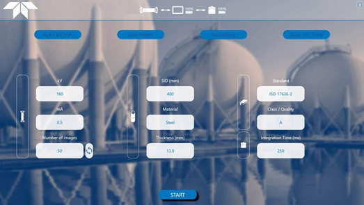
Photo 2 (SHERLOCK Software / Screen)
4.3. Image Acquisition and Processing: CR images are obtained by passing the IP through a laser scanner that digitizes them and sends them to a computer for later analysis.
In DR the images go directly from the flat panel (DDA) to the computer.
4.4. Image visualization and analysis: using software specifically developed by the manufacturers of this equipment, the quality of the acquired images is controlled (sensitivity, contrast, definition, noise, resolución, etc.) to compare them with those required according to the application code or standard. This specific software allows to improve, enlarge, and perform measurements, from the raw image received (Photo 3 and 4).
The acquired images can be sent for evaluation to a distant computer as well, where the corresponding evaluation can be carried out, and/or validate the one already carried out.
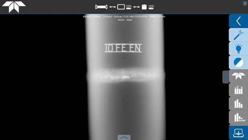
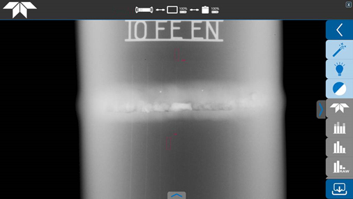
Photo 3 and 4 (images acquired with DR ready to be analyzed and evaluated)
4.5. Image quality – Sensitivity: the technological advances incorporated into digital radiography techniques, from 30 years ago to the present day, mean that we can affirm that their sensitivity is at least equivalent to FR, in many cases better and they comply with the requirements of Image quality of the international application code ASME V – Art.2 & ISO 17636-2.
4.6. Image Storage: the acquired images can be saved in digital files and stored on any computer or device in commercial or specific formats for digital radiography techniques (i.e. DICONDE).
5. Cost.
The cost of the equipment necessary for Digital Radiography techniques (CR or DR) is initially more expensive than for Conventional Radiography (FR), but depending on the use, the optimization of the resources involved, the advantages and benefits inherent to the same already detailed, its amortization is achieved quickly, with the additional benefit of later keeping a durable asset (equipment) for a long time (see 3.3).
Cost per hour → DR ˃ CR ˃ FR (see Table 4).
Cost per tube/weld → DR ˂ CR ˂ FR (see Table 4).
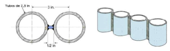
6. Practical case.
Tubes Ø 2”- 6.3 mm.- A 106 Gr.B.- similar to waterwall were practically examined by DR, using the following equipment:
RX Generator (TELEDYNE ICM) CP160B, a Flat Panel (DDA) GO-SCAN 1510 HR (99 µm – CMOS) and SHERLOCK Software.
- Exposure times and other parameters were theoretically calculated for the other techniques, in all cases density 2 was considered.
- For Ir 192 and Se 75, 30 Ci activities were considered. and density 2 in both cases too.
In all cases “Perpendicular” technique (3 exposures at 60 °) – DFP = 40 cm, in accordance with ISO 17636-1 / 2 (class A), the results obtained being:
| FILM D7 | CR IP S | DR DDA | Ir 192-D7 | Se 75-CR IP S | |
| Table 3 | 5 min | 5 min | 20 sec | 1.65 min | 3.75 min |
| Table 4 | Duty Cycle x 2 Pipes / Welds x Image | ||||
| Pos 1 | 5 min | 5 min | 20 sec | 1.65 min | 3.75 min |
| Pos 2 | 5 min | 5 min | 20 sec | 1.65 min | 3.75 min |
| Pos 3 | 5 min | 5 min | 20 sec | 1.65 min | 3.75 min |
| Mob/Prep. | 4 min | 4 min | 4 min | 2 min | 2 min |
| Processed | 8 min | 5 min | N/A | 8 min | 5 min |
| Total | 27 min | 24 min | 5 min | 14.95 min | 18.25 min |
| Tubes/hour | 4.5 | 5 min | 24 | 8 | 6.5 |
7. Conclusions.
| INDICATOR | FILM D7 | CR IP S | DR DDA | Ir 192-D7 | Se 75-CR IP S |
| Safety | 3 | 2 | 1 | ||
| Radiation | 3 | 2 | 1 | ||
| Exposure time | 2 | 2 | 1 | ||
| Film / Image processing | 2 | 1 | |||
| Image quality – Sensibility – Resolution | 2 | 3 | 1 | ||
| Image storage | 2 | 1 | 2 | ||
| Initial Cost | 2 | 2 | 3 | 1 | 1 |
| Productivity | 4 | 3 | 1 | 2 | |
| MORE RECOMMENDABLE | RECOMMENDABLE | LESS RECOMMENDABLE | |||
This article has been written by Teledyne ICM’s independent agent in Argentina, José G. Caprarulo – josecaprarulo@yahoo.com